
In this brief post I would explain basics of interfacing SHAULA-V9 with any compatible security alarm system. SHAULA -V9 is a GSM/GPRS gateway that works as GSM and SMS gateway for security systems.
It is designed to be easily interfaced with a number of alarm security panels for example Pyronix 816 which I would use in the next post. In this post I would show the Interface of SHULA-V9 , focusing on the V9 ports. Lets start by knowing the different ports.

-
- 2 Connector for power (12V DC)
- 8 (4+4) pin connectors for communication with alarm security system.
- 2×10 pin connector for SHAULA-701.
- Communication Port (Rs-485)
- Gate Relay Pins ( NC- C – NO)
- Door Relay Pins ( NC- C – NO)
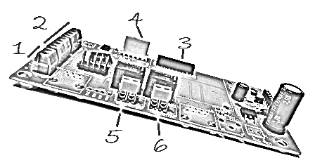
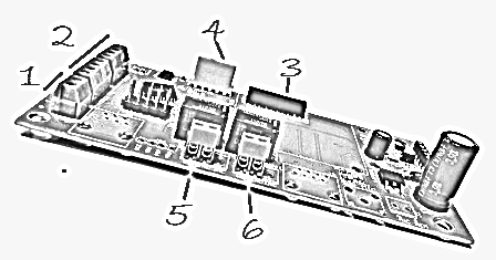
Connector labelled 1:
The connector labelled 1 above is used to power SHAULA-V9. It requires 12V as a standard. Its important to note down the polarity. Its clearly marked out. GND should connect to - and Positive 12 V to +. If using a CAT-5 cable to connect to security board use BLUE wire to + and BLUE-WHITE to -.
Connectors labeled 2:
SHAULA-V9 is designed to use a single Cat-5 cable to interface to security control panel. The ports on connector 2 are marked for Cat5 cable colors.
Connectors labeled 3:
SHAULA-V9 is designed to work with SHAULA-701 which is a required part which connects through this connector.
Connectors labeled 4:
This port is reserved for Rs-485 based communication along with GND ,12V, Gate and Door Signals. In general use it isn’t used.
Connectors labeled 5:
This connector is used as outputs of Gate Relay.
Connectors labeled 6:
This connector is used as outputs of Door Relay.
There are some other ports which I haven’t covered in this post, these are reserved for testing and development purposes. In the next post I would explain how to interface SHUALA-V9 with Pyronix Matrix-816 and programming Matrix-816 for the purpose.
Recent Comments