
INTRODUCTION
SHAULA-V10 is a GSM gateway that can provide SMS and Call features for different Alarm systems. The features and functions may vary with firmware versions slightly but in general they are consistent. Below is the summary of features.
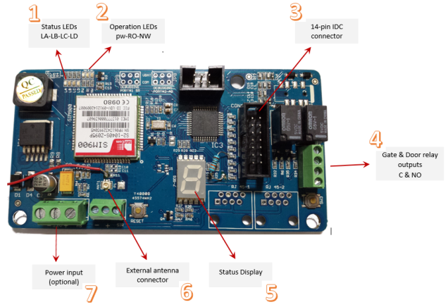
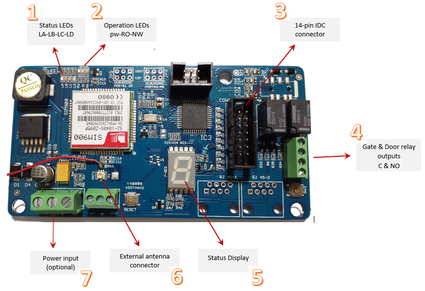
In the figure above SHAULA-V10 is shown labelled for important parts , we would explain these parts one by one .
1: STATUS LEDs
This is group of four LEDs that indicate different states and provide important information. Its important to understand these, as these can be very helpful in debugging and troubleshooting. The four LEDs are RED, GREEN, ORANGE and BLUE marked LA, LB ,LC and LD respectively.
2: OPERATION LEDs
This is group of three LEDs that indicate different operational states states of SHAULA-V10. The three LEDs are RED, BLE and GREEN marked PW, RI, and NW respectively.
3: IDC CONNECTOR
In order to work properly,SHAULA-V10 requires a few signals to work with , which should be made available on the IDC connector .The IDC connector is a 14 pin (2×7) connector. The pin-outs are as follows. (PIN One is marked as red)
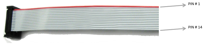
IDC Cable
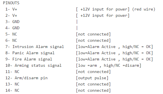
PINOUTS
4: GATE AND DOOR RELAY OUTPUTS
SHAULA-V10 can control gate and door using two on board relays. Common and Normal Open signals of both the relays are provided on this connector. Use`N01 and NC1` outputs for gate and `N02 and NC2` outputs for gate.
5: STATUS DISPLAY
This display helps in debugging and troubleshooting , It indicates different states of the operations, It shows when an SMS is received or sent , call is received or made, etc
| DISPLAY |
OPERATION STATUS |
PROGRAMMING STATUS |
|
SHAULA-V10 initializing and is not yet ready |
Admin number is not yet programmed |
|
 |
SHAULA-V10 initializing and is not yet ready |
Admin number is programmed |
 |
SHAULA-V10 is trying to register to network | Admin number is not yet programmed |
 |
SHAULA-V10 is trying to register to network | Admin number is programmed |
 |
SHAULA-V10 is now in registered to network section* | Admin number is not yet programmed |
 |
SHAULA-V10 is now in registered to network section* | Admin number is programmed |
 |
incoming Call(SHUALA-V10 is receiving a call) | N/A |
 |
Outgoing Call (SHUALA-V10 is making a call) | N/A |
| incoming SMS (SHUALA-V10 has received SMS) | N/A | |
 |
Outgoing SMS (SHUALA-V10 is sending SMS) | N/A |
* even if the SIM card has not yet, The operation for registered to network condition has started.
6: EXTERNAL ANTENNA CONNECTOR
In some cases where signals at the SHAULA-V10 location are weak , an external antenna can be connected. A U.Fl antenna connector is thus provided.

7: POWER CONNECTOR
A connector is available for providing the power via a screw terminal connector.
Recent Comments