
THIS GUIDE WILL WORK FOR SHAULA-791 as well”
INTRODUCTION
SHAULA-V10/SHAULA-791 is a GSM gateway that can provide SMS and Call features for different Alarm systems. The features and functions may vary with firmware versions slightly but in general they are consistent. Below is the summary of features.
- operate gate and door (via two relay on board with C and NC contacts).
- arm & disarm alarm control panel using the app.
- make alert calls in case of intrusion alarm, panic alarm or fire alarm.
- monitor power source notify by SMS if it goes or when it comes back.
- monitor backup battery when main power is absent and notify by SMS if battery is low.
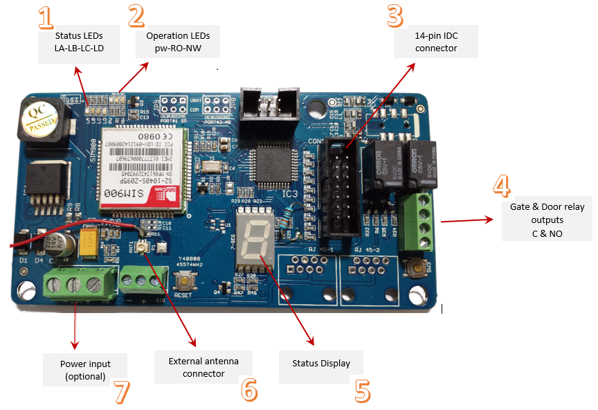
In the figure above SHAULA-V10(SHAULA-791 is basically similar) is shown labelled for important parts , we would explain these parts one by one .
1: STATUS LEDs
This is group of four LEDs that indicate different states and provide important information. Its important to understand these, as these can be very helpful in debugging and troubleshooting. The four LEDs are RED, GREEN, ORANGE and BLUE marked LA, LB ,LC and LD respectively.
- LA (Red) : Indicates state of intrusion alarm input. If the input at pin-7 of IDC connector is Low this LED will be ON, which indicates that SHAULA-V10/SHAULA-791 received an Intrusion alarm signal from the alarm system.
- LB (Green) : Indicates state of panic alarm input. If the input at pin-8 of IDC connector is Low this LED will be ON, which indicates that SHAULA-V10/SHAULA-791 received a panic alarm signal from the alarm system.
- LC (Orange) : Indicates state of fire alarm input. If the input at pin-9 of IDC connector is Low this LED will be ON, which indicates that SHAULA-V10/SHAULA-791 received a fire alarm signal from the alarm system.
- LD(Blue) : Indicates state of arming. If the input at pin-10 of IDC connector is Low this LED will be ON, which indicates that SHAULA-V10/SHAULA-791 received a signal from the alarm system indicating that the system is Armed, when this LED is OFF it indicated the system is disarmed.
2: OPERATION LEDs
This is group of three LEDs that indicate different operational states states of SHAULA-V10/SHAULA-791. The three LEDs are RED, BLE and GREEN marked PW, RI, and NW respectively.
- PW(Red) : Indicates power status of SHAULA-V10 as soon as power is applied to SHAULA-V10/SHAULA-791 this LED will be ON, If the power is not applied it will be OFF.
- RI(Blue) : Indicates state of incoming SMS or Calls. Its equivalent to the ringer of a phone. It will be ON when there is an incoming call and will blink once for an SMS received.
- NW(Green) : Indicates state of network connection.
- Flash@inverval 800ms: GSM not yet registered to cell phone network.
- Flash@inverval 3000ms: GSM registered to cell phone network.
3: IDC CONNECTOR
In order to work properly,SHAULA-V10/SHAULA-791 requires a few signals to work with , which should be made available on the IDC connector .The IDC connector is a 14 pin (2×7) connector. The pin-outs are as follows. (PIN One is marked as red)
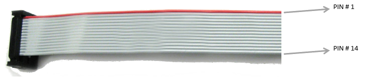
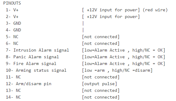
- V+ : Its the first pin of the cable ,denoted by the red wire in the cable, the second wire is also the same V+, It can accept 9V-24VDC input. It is recommended to use 12V or 9V.
- GND: Its the ground wire.
- NC: not connected, Do not connect this wire.
- Intrusion Alarm signal : its the 7th wire, If the wire has a Low signal , SHAULA-V10/SHAULA-791 identifies an intrusion Alarm and will switch on LED LA as explained in the Status LEDs section. If the signal is not Low , LED LA will be OFF indicating no Intrusion alarm.
- Panic Alarm signal : its the 8th wire, If the wire has a Low signal , SHAULA-V10/SHAULA-791 identifies a panic Alarm and will switch on LED LB as explained in the Status LEDs section. If the signal is not Low , LED LB will be OFF indicating no panic alarm.
- Fire Alarm signal : its the 9th wire, If the wire has a Low signal , SHAULA-V10/SHAULA-791 identifies a fire Alarm and will switch on LED LC as explained in the Status LEDs section. If the signal is not Low , LED LC will be OFF indicating no Fire alarm.
- Arming Status signal : its the 10th wire, If the wire has a Low signal , SHAULA-V10 identifies that the Alarm system is Armed and will switch on LED LD as explained in the Status LEDs section. If the signal is not Low , LED LD will be OFF indicating system is disarmed.
- Arm disarm pin: It is an output pin and will provide a pulse of Low signal in order to Arm or disarm the Alarm system.
4: GATE AND DOOR RELAY OUTPUTS
SHAULA-V10/SHAULA-791 can control gate and door using two on board relays. Common and Normal Open signals of both the relays are provided on this connector. UseN01 and NC1 outputs for gate and N02 and NC2 outputs for gate.
INTERFACING WITH PYRONIX MATRIX-816
As an example we would show settings and connections for Pyronix Matrix-816. Its important that all programming and connections are made correctly , Otherwise SHAULA-V10/SHAULA-791 wont be able to function correctly.
First we would program the programmable outputs of Matrix-816, Using the keypad make the following settings in Pyronix PGM settings on Page 16 function 8.1 of the Pyronix Matrix-816 manual.
PGM3---16
PGM4---11
PGM5---10
PGM6---04

Set output states of PGMs as per page-17 of the programming manual, Set PGM-3,PGM-4,PGM-5, PGM-6 all as off (default is OFF)

Finally we would set one zone to work as key-switch, we would use last zone “zone 8” to work as keys-witch, you may use any other zone as well. To do so make the following programming in Matrix-816
- as on page 7 function 3.2.1 set
program 258as 11 “Mometary keyswitch” - as on page 4 function 270 set zone 8 as NO “normally open” by default it’s set as NC “normally close”


WIRING
In the image below its shown how to connect IDC pins to Matrix-816 for the programming shown above.

hope this was helpful. Please feel free to reply if you need any more information
Admin